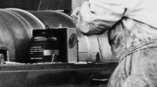
Yes, they're full of baking soda and they're mounted alongside the jetpipe on the left hand side under the tail cover. If you look in the DeLara colour book there's a pic of K7 in 66 with the top covers off and they're clearly visible. There's even a Pyrene van parked in the yard.
They are filled through a fitting in the bottom of the bottle and charged with gas from there too. The top has a foil seal with a jam-pot cover over it. The covers are held down with a length of fuse wire so when you make the circuit it burns through, the pressure inside bursts the foil seal and throws the jam-pot cover out of the way and out goes your fire once the baking soda gets down the copper pipe from the plumber's merchants.
Technical Talk
-
Renegadenemo

- Posts: 5176
- Joined: Mon Dec 01, 2008 12:29 pm
- Location: N E England
- Contact:
Re: Technical Talk
I'm only a plumber from Cannock...
"As to reward, my profession is its own reward;" Sherlock Holmes.
'It ain't what they call you, it's what you answer to.' W.C. Fields.
"As to reward, my profession is its own reward;" Sherlock Holmes.
'It ain't what they call you, it's what you answer to.' W.C. Fields.
Re: Technical Talk
Yes, the pic with the Pyrene van is mine (!!), but I am not at home (and wont be for five weeks) so no access. I;ll try a post a Crusader schematic later.
From the size of the bottles, wouldn't have been much of a "hit" !!
Having just looked, the schematics for K7 show two bottles, both on the port side, next to each other, is that right?
From the size of the bottles, wouldn't have been much of a "hit" !!
Having just looked, the schematics for K7 show two bottles, both on the port side, next to each other, is that right?
Steve Holter, UK and France, and sometimes reality....................
-
Renegadenemo
- Posts: 5176
- Joined: Mon Dec 01, 2008 12:29 pm
- Location: N E England
- Contact:
Re: Technical Talk
Yup, that's them. They're manifolded together and attached at the other end in a frame. As soon as I can find the pic's I'll post a few but I've archived them an I'm struggling.Having just looked, the schematics for K7 show two bottles, both on the port side, next to each other, is that right?
I'm only a plumber from Cannock...
"As to reward, my profession is its own reward;" Sherlock Holmes.
'It ain't what they call you, it's what you answer to.' W.C. Fields.
"As to reward, my profession is its own reward;" Sherlock Holmes.
'It ain't what they call you, it's what you answer to.' W.C. Fields.
-
Dangermouse
- Posts: 118
- Joined: Tue Aug 10, 2010 9:59 pm
Re: Technical Talk
Also lifting the engine cover off will expose the fire to a lot more oxygen... A plumbed-in system means that you can keep all the panels on, which will help starve the fire of oxygen and also contain the extinguisher contents where they're needed.quicksilver-wsr wrote:A built-in system is essential for anyone who's serious about safety. A fire, if it starts, is likely to start under the engine-cover, so even if there's a properly-equipped safety crew available externally for rapid reaction, by the time you get the (by now red-hot) engine-cover off to get to the fire's source, the boat will most probably be very poorly indeed.
I'm not frightened of fire, but have always had a healthy respect for it, due to the havoc it can wreak in a very short space of time. As a consequence, there's even a fire-extinguisher in the boot of my trusty Vauxhall Astra!
Nigel
I had an extinguisher clipped into its holder next to the bonnet release catch on my Discovery, reasoning that it was easy to grab there if helping someone else. Also fitted my engine fire plan to pull the catch, then dump the contents of the extinguisher through the gap after the bonnet had popped up onto the safety latch.
Matt in Mid Wales
-
Renegadenemo
- Posts: 5176
- Joined: Mon Dec 01, 2008 12:29 pm
- Location: N E England
- Contact:
Re: Technical Talk
I'd be over the moon if my Discovery caught fire - that would fix every one of its multitudinous faults all at once - but I digress.I had an extinguisher clipped into its holder next to the bonnet release catch on my Discovery
I finally found some of the fire system pic's. I had a major IT calamity a month or so ago and, though I didn't lose any data, I now can't find stuff as efficiently as once I could but it's coming back.
This is the fire system in one big clump as we removed it from the wreck. Notice the manifold linking the bottles at the top.
I have pic's of it still bolted in-situ - will dig 'em out - but above is what they looked like when dragged out of the plastic crate we threw them into in 06 when we gutted the hull.
The hardware is very heavily built - as you'd expect with a system designed for a fighting vehicle - just look at the lavish use of heavy stuff on Richie's little tank and you can see that engineers involved in such projects didn't pay too much heed to weight-saving. The manifold that spans the tops of the bottles is cast in brass with soldered-in screens to break up the suppressant powder as it left in a hurry. This item laughed at 34 years in a lake then Checkie shone it up to a nicety...
The bottles themselves are heavy, steel containers pressurised to only 50bar-ish which, considering the wall thickness of the cylinders and their small inside surface area, means they should be everlasting. We do have a little hot-work to do on them and some puzzling over how to refill and rework them so they'll perform again. Don't worry - we'll not not be relying on them to put fires out but we will test-fire them one last time just so you can see what might have happened. Then we'll fit a proper system for when we have ten years of our damned hard work floating out on the lake with a gas turbine spinning inside it.
Notice that in bold letters it says that it's 'Government Property' (on a background of green) so goodness knows where DMC scrounged it up.
PS - Steve, if you need anything at all on the fire system for your research just say the word.
You do not have the required permissions to view the files attached to this post.
I'm only a plumber from Cannock...
"As to reward, my profession is its own reward;" Sherlock Holmes.
'It ain't what they call you, it's what you answer to.' W.C. Fields.
"As to reward, my profession is its own reward;" Sherlock Holmes.
'It ain't what they call you, it's what you answer to.' W.C. Fields.
Re: Technical Talk
Superb, thanks Bill, they look smaller than Crusader's and actually look smaller than what I thought was fitted to K7
but that may just be due to the angle thee photo is taken from? Anyway, they are smaller than K6's which according to spec's, are HUGE!!!

but that may just be due to the angle thee photo is taken from? Anyway, they are smaller than K6's which according to spec's, are HUGE!!!
Steve Holter, UK and France, and sometimes reality....................
-
Renegadenemo
- Posts: 5176
- Joined: Mon Dec 01, 2008 12:29 pm
- Location: N E England
- Contact:
Re: Technical Talk
That's a useful looking pic for reference purposes - any chance we could have a bigger copy so we can get the installation looking spot-on when the time comes? It won't go any further.
Working on sponson noses and sealing strips this weekend. The lifting brackets for the main spars are on the agenda too so it's going to be a busy one.
Working on sponson noses and sealing strips this weekend. The lifting brackets for the main spars are on the agenda too so it's going to be a busy one.
I'm only a plumber from Cannock...
"As to reward, my profession is its own reward;" Sherlock Holmes.
'It ain't what they call you, it's what you answer to.' W.C. Fields.
"As to reward, my profession is its own reward;" Sherlock Holmes.
'It ain't what they call you, it's what you answer to.' W.C. Fields.

Drag struts...
Not too sure if this has been covered elsewhere or not, but here goes.
Whilst reading the September (2014) diary entry I noted the mention that Ken Norris notated the struts on the sponsons as 'drag' struts and also the mention that they work in compression and that "we can forgive him that one" which puzzled me for all of 2 seconds and results in the query below.
My query is this:
When running on the 'points' at the rear of the sponson/s and when the associated force/s will want to pull the nose of the sponson down as a result of that, the struts are surely under a 'drag' force (Id-Est in tension)?
Of course, before getting onto the sponson points, the force is in the opposite direction, pushing up the front of the sponson, thus the struts are in compression.
I may not be an engineer, however to me personally, it seems that the struts are indeed 'drag' struts, although I am open to correction.
Just cos my username is Thunderer, doesn't necessarily mean I SHOUT !!
"A vehicle is designed to be used, restored or otherwise" A personal response on the question "you have just restored it, why use it?"
"A vehicle is designed to be used, restored or otherwise" A personal response on the question "you have just restored it, why use it?"
-
Renegadenemo
- Posts: 5176
- Joined: Mon Dec 01, 2008 12:29 pm
- Location: N E England
- Contact:
Re: Technical Talk
There's much aircraft terminology in Ken's work and I suspect we're seeing a little more of it here. Maybe a 'drag strut' is a piece of aeroplane and the description on K7's drawing has more to do with the type of component it is rather then the precise way in which it does its job because it is always in compression.I may not be an engineer, however to me personally, it seems that the struts are indeed 'drag' struts, although I am open to correction.
The most annoying one is the planing 'shoes', which are actually the plates from under the sloping forward part of the sponsons. They are so called presumably because they resemble the front part of the sole of a shoe in plan-form, but over the years the name has been incorrectly applied to the wedges, which are just that and are the aft part of the planing surface - never mind, that doesn't really matter either.
I'm only a plumber from Cannock...
"As to reward, my profession is its own reward;" Sherlock Holmes.
'It ain't what they call you, it's what you answer to.' W.C. Fields.
"As to reward, my profession is its own reward;" Sherlock Holmes.
'It ain't what they call you, it's what you answer to.' W.C. Fields.

Re: Technical Talk
In aviation terminology the term "drag strut" is applied equally to describe a strut that is loaded in compression or a strut that is loaded in tension (probably because most components in an aircraft structure are likely to be subjected to load reversals in any case). What defines a drag strut is that it transfers a lateral load from one part of the structure to another.Renegadenemo wrote:There's much aircraft terminology in Ken's work and I suspect we're seeing a little more of it here. Maybe a 'drag strut' is a piece of aeroplane and the description on K7's drawing has more to do with the type of component it is rather then the precise way in which it does its job because it is always in compression.I may not be an engineer, however to me personally, it seems that the struts are indeed 'drag' struts, although I am open to correction.
As the load transferred to the spar must have some lateral component, I would say that Ken Norris was correct.
Obstacles are those frightful things you see when you take your eyes off your goals.